When it comes to towing, one of the preeminent priorities that cannot be overemphasized is the wiring of the trailer electrical system. A trailer wiring diagram is an extremely useful tool when you need to hook up the trailer to your car because it shapes the whole process and illustrates how you are to connect the lights and brakes of the trailer to the car. For the beginner, this is something you will have to study in detail as a towing expert. Safety and efficiency in towing depend on these trailer wiring diagrams.
What is trailer wiring diagram?
A trailer wiring diagram is an electrical drawing of the manner in which trailer wiring is connected to the trailer harness.
A trailer wiring diagram is therefore a representation of the wiring system in a trailer and is quite essential in identifying the right connections. They illustrate how each wire is linked and through which area it passes, and then they provide an indication of how all lights, brakes, and other electric components work as required. These diagrams help you comprehend where to place and how to join in order to acquaint your trailer
Why do you need a trailer wiring diagram?
1. Safety: Hearse must be properly wired trailers to enhance road safety standards. Every light and signal should be checked to avoid mishaps that may be a result of the failure of these components or aiming at enhancing the visibility of the interior of the vehicle.
2. Compliance: For instance, the legal regulation concerning trailers stipulates that all lights and signals must be in functional condition. It is a wiring diagram that can help you ensure that they meet these requirements.
3. Efficiency: Knowing the wiring layout might be important in avoiding repeated work time while attempting to implement additional wiring changes or fix some faults.
4. Troubleshooting: It also provides a clear procedure on how to check if something is wrong with the circuits because, with the wiring diagram, you can easily find the faults.
Subsystems of a Trailer Wiring System
Before diving into the diagrams, it’s essential to understand the key components involved in trailer wiring:
1. Connector Plugs: These are used for wiring in the electricity system between the trailer and the towing vehicle. Their classifications include 4-way connectors, 5-way connectors, 6-way connectors, and 7-way connectors.
2. Wires: Each of the colored wires may depict a particular brake or turn signal light, or a tail light among others.
3. Ground Wire: It performs the function of providing the much-needed wire connection for everything to work as it should.
4. Fuses and Relays: These messes protect the electrical system against damages that may arise from overloads or short circuits.Common Trailer Wiring Diagrams
Here are some standard trailer wiring diagrams you might encounter:
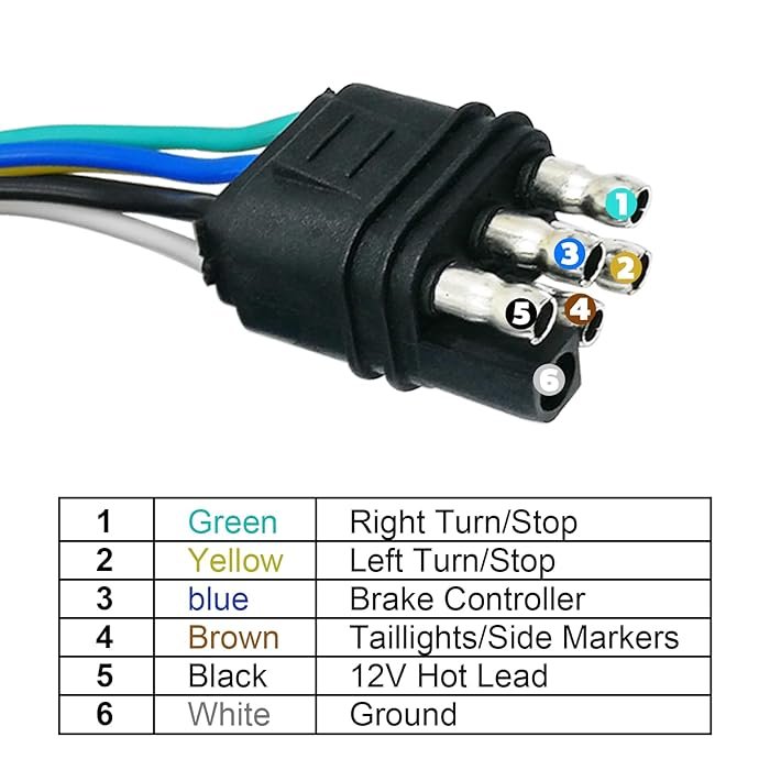
4-Pin Connector

4-Pin trailer wiring diagram:

The basic pattern is a 4-way connector that is primarily used for light trailers that do not come with the brake system. It was designed with four connection points or pinheads, each having specific roles in operating the equipment.
- White: Ground wire – The ground wire is used to ground the DC circuit and the frame of the trailer.
- Brown: Turning lights – the lights that illuminate the trailer during turnover.
- Yellow: Writing lamp/turn signal – it is responsible for operating the writing lamp and the turn signal.
- ·Green: Rear combination lights switch – controls the rear combination lights which include the turn signals and the brake light.
Usage: Suits simple trailer uses like utility trailers or boat trailers, those that do not have any electric brakes
5-Pin Connector

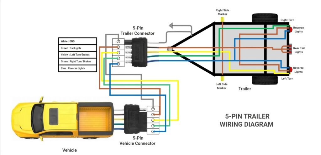
5 pin connector trailer wiring diagram:

The 5-way connector incorporates another wire to manage trailers with surge brakes of reverse lights. This type includes five five-pin terminals which may also be referred to as five connection points.
- White: Ground wire – very important when it comes to electrical installation.
- Brown: Tail/running lights – turn on the tail lights of the trailer, and enhance the running lights of the vehicle.
- Yellow: The left side turn /stop signal – turns on the left turn signal and the brake light.
- Green: Right turn signal/brake light – lights that indicate a car is turning right and serve as a brake light.
- Blue: Electrical: Electrics for usage of electric brakes or other purpose.
Usage: Usually for trailers used for boats and small utilities along with having more power demands than a standard trailer.
6-Pin Connector

6 pin connector trailer wiring diagram:

Hence, the 6-way connector is used for trailers that have electric brakes and other complicated electrical connections. It has six pins or terminals, which are commonly known as contacts.
- ·White: Ground wire – ensures the back flow of electricity in case of a fault.
- ·Brown: A Tail running lights – provides for the trailer’s tail lights.
- ·Yellow: Left turn signal/brake light – used for introducing turn signals mainly on the left side of the automobile together with the brake light.
- ·Green: Right turn signal/brake light – In Charge of commanding the right turn signal and the brake light.
- ·Blue: Electric brake switch – activates the circuit of the trailer’s electrical brakes.
- ·Red or Black: Auxiliary power – this power is used for illuminating the interior parts of the trailer or the accessories.
Usage: Applicable for medium-sized trailers especially Horse trailers, utility trailers, and the ones with electric brakes.
7-Pin Connector

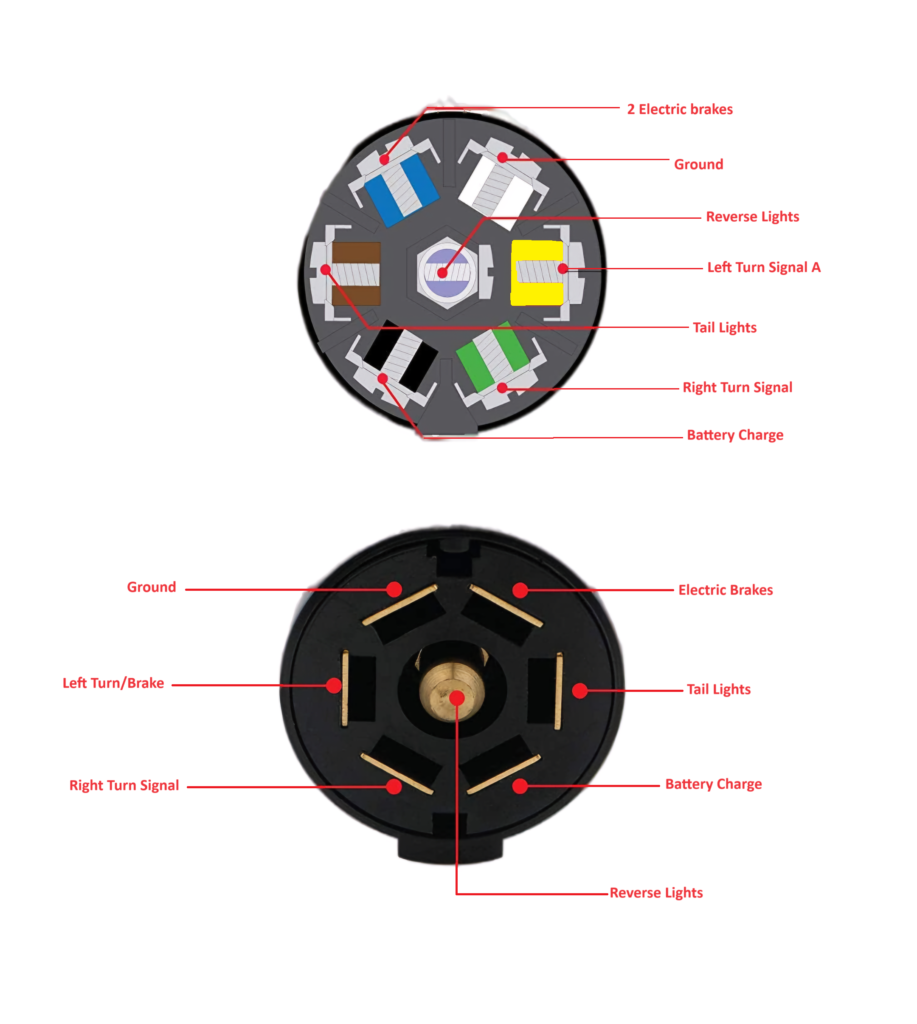
7 pin connector trailer wiring diagram:

The 7-way connector is the most versatile since it can handle the requirements of numerous electrical devices in the trailer. It has a total of seven pins or terminals and is defined as a special I/O pin for signaling that an input has occurred.
- White: Ground wire – is used to complete the circuit.
- Brown: Tail/running lights – connected to the power circuit which powers the trailer’s tail lights.
- Yellow: Left turn signal A-. Controls the left turn signal and brake light.
- Green: Right turn signal/brake light – operates the right turn signal and brake light on the car.
- Blue: Electric brake – is involved with the powering of the trailer’s electric brakes.
- Black: Battery charge or auxiliary power – this position charges the trailer’s battery or powers other auxiliary applications.
- Grey/Purple: Back up – turns on the trailer’s reverse lights.
Usage: Usual for big trailers, RVs, and multiple electrical systems trailers.
Detailed Steps to Wire Your Trailer
1. Identify Your Needs: Click on the picture or go to the manual to find out which sort of connector type and wiring structure will be adequate based on the details of your trailer. They all must have a couple r; a single-axle trailer without the brakes will need 4 4-way flats and a much larger trailer that would take much more electricity will need 7 7-way flats.
2. Gather Materials: Be in a position to confirm that you have the right connector and wires and have installed the right electrical tapes, and wire stripper, and the multi meter should have the capability of testing various voltages.
3. Prepare Your Work Area: It will also be wise to park your trailer and the vehicle in an area that has a relatively flat surface to ensure that you have easy handling of the trailer. When it comes to cars some of them have their battery in their hood so in a situation where the car is being shot in areas that may result in short-circuiting remove the fuse that leads to the battery then remove the car battery.
4. Strip and Connect Wires: With this, first-timers in auto wiring should strip the wires following the Wiring diagram’s Colored Code to identify the connection. They are wire nuts or crimp connectors, however, before connecting it the end must be crimped and covered by an electrical tape, they are the best to make the connection.
5. Secure the Wires: The wires should then be fixed to the frame of the trailer; one may opt for screws but it will suffice to close the wires by use of zip ties or clips. When it comes to concerning the structural aspects of the product as an object it is advisable not to provide any cutting-edge or dynamic framework to intervene with the electrical wiring.
6. Reconnect the Battery and Test the System: Only ensure that all the wires have been fixed before reconnecting the battery of the car back. They include: activating all the lamps including the cautionary lamps the direction lamps, and the stopping lamps. Confront someone for looking at the lights while you are concerned with the handlebar and other facets of the car otherwise known as the prosthetics.
Troubleshooting Tips
- ·Check Connections: Check and confirm that all connections should be tight and should not be corroding. The absence of tight washers and / or the deterioration of the connections can result to electrical faults.
- ·Test with a Multi meter: This can be done using a multi meter where continuity tests and correct voltage should be checked. It would also help you to know where probably the problem could be with references to wiring.
- ·Inspect Fuses and Relays: If you find a component does not work, look into the fuse and relays located in the automobile’s fuse box. Replace any burnt out fuses and/or faulty relay.
- ·Look for Damaged Wires: At some time the wires have to be replaced since they may get damaged or develop some frays. Check all the wiring harness from end to end and correct or replace any that have been damaged.
Advanced Tips for Trailer Wiring
- Use Heat Shrink Tubing: For a more durable and leak proof connection, use heat shrink tubing over line connectors.
- Install a junction box: A junction box can help organize and cover connections, especially in campers with complex wiring system.
- Upgrade to LED Lights:LED lights are more durable and energy-effective compared to traditional incandescent bulbs
- Regular Maintenance:check your caravan’s wiring system for wear and tear and gash. This can help avoiding issues before they come serious problems.
Conclusion
Understanding and using a trailer wiring diagram can make the difference between a smooth towing experience and a frustrating one. By following the right diagram and ensuring proper connections, you can ensure safety, compliance, and efficiency every time you hit the road with your trailer.
